Device Setup Instructions
What you’ll need
- 1x Raspberry pi 4
- 1x Canakit RPI4 GPIO ribbon cable
- 1x Canakit GPIO T connector
- 3x Generic GPIO buttons
- 1x Blue LED
- 1x Red LED
- 1x 16x2 Canakit grid display
- 3x 10kΩ resistors (BROWN, BLACK, ORANGE, GOLD)
- 2x 220Ω resistors (RED, RED, BROWN, GOLD)
- 1x Potentiometer
- 24x Dupont cables
- 1x I2C ADAFruit AHT20 Temperature & Humidity Sensor
Before we go any further place your T connector at the top of your GPIO breadboard. Connect the T connector to the RPI GPIO pin set. Finally connect the AHT20 sensor via I2C on the RPI itself.
Wiring Instructions
Wiring the display
- Place the 16x2 Canakit grid display with the left most pin at D44. The remainder of the pins will fall into place.
- Run a Dupont cable from E44 to any GND (Ground) pin.
- Run a Dupont cable from E45 to the POSITIVE 5V rail.
- Run a Dupont cable from E46 to F46.
- Run a Dupont cable from E47 to GPIO pin 17.
- Run a Dupont cable from E48 to any GND pin.
- Run a Dupont cable from E49 to GPIO pin 27.
- Run a Dupont cable from E54 (which is the D4 pin on the screen) to GPIO pin 5.
- Run a Dupont cable from E55 to GPIO pin 6.
- Run a Dupont cable from E56 to GPIO pin 13.
- Run a Dupont cable from E57 to GPIO pin 26.
- Run a Dupont cable from E58 to POSITIVE 5V rail.
- Run a Dupont cable from E59 to GND pin.
Wiring the potentiometer
- Run a Dupont cable from F45 to GND pin.
- Run a Dupont cable from F47 to POSITIVE 5V rail.
- Place the poteniometer so the three pins fall into G45, G46, and G47.
Wiring the LEDs
- Place the blue LED positive leg in I54 and the negative leg in I53.
- Place the red LED positive leg in G60 and the negative leg in G59
- Run a Dupont cable from F60 to GPIO pin 18.
- Place a 220Ω resistor on J59 to J55
- Run a Dupont cable from F55 to GND pin.
- Place a 220Ω resistor on G53 to G49
- Run a Dupont cable from J49 to GND pin.
- Run a Dupont cable from F54 to GPIO pin 23.
Wiring the buttons
- Place a 10kΩ resistor from POSITIVE 3.3V rail to B29.
- Place a 10kΩ resistor from POSITIVE 3.3V rail to B35.
- Place a 10kΩ resistor from POSITIVE 3.3V rail to B39.
- Place a red button so that the pins on the left side fall on D27 and D29.
- Place a green button so that the pins on the left side fall on D33 and D35.
- Place a blue button so that the pins on the left side fall on D39 and D41.
- Run a Dupont cable from H27 to GPIO pin 25.
- Run a Dupont cable from H29 to GND pin.
- Run a Dupont cable from H33 to GND pin.
- Run a Dupont cable from H35 to GPIO pin 24.
- Run a Dupont cable from H39 to GPIO pin 12.
- Run a Dupont cable from H41 to GND pin.
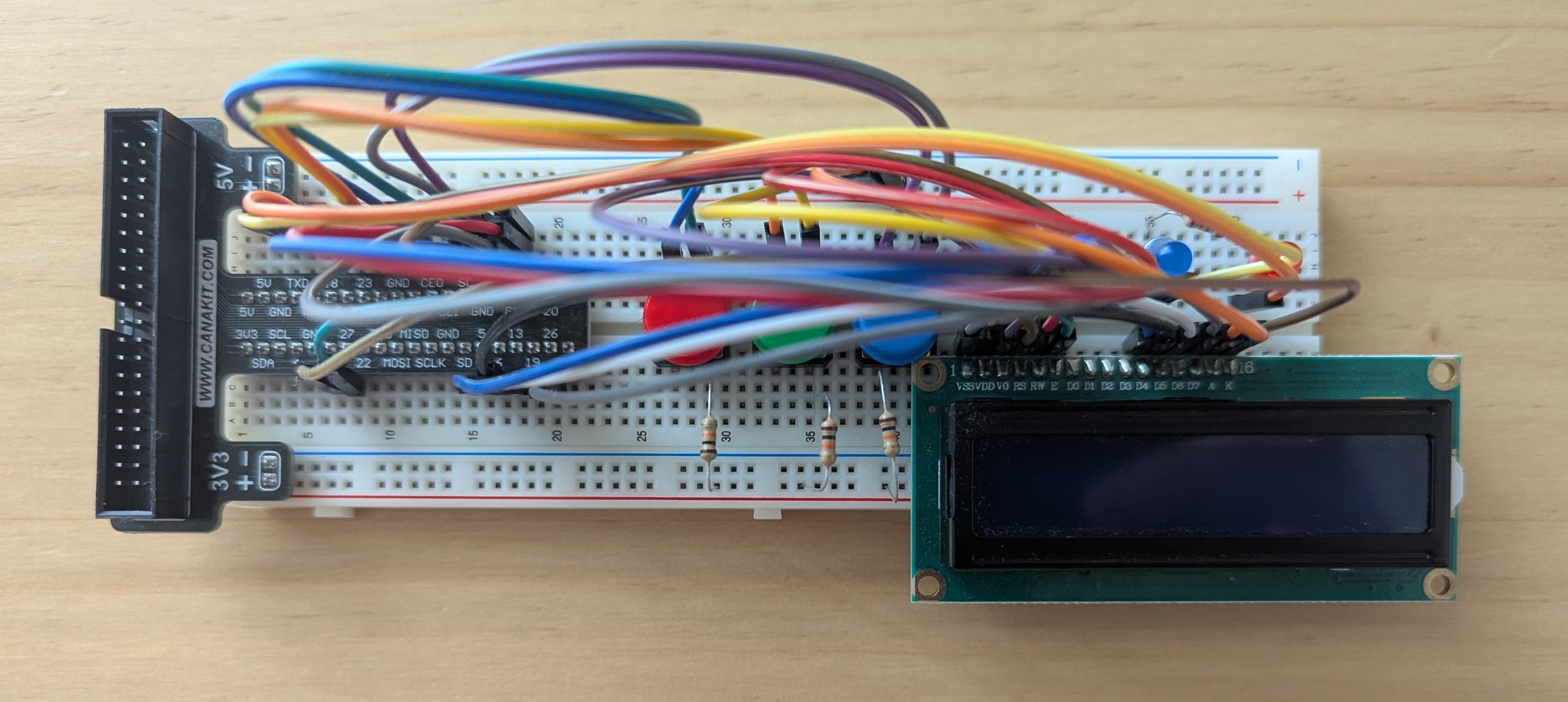
Congratulations, you’ve setup the entire device and should look something like this: